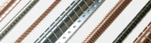
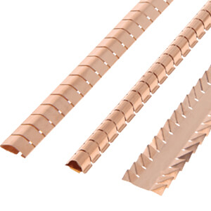
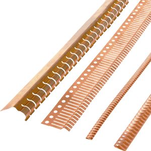
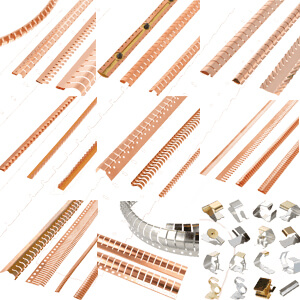
Fingerstrip gaskets and metal grounding products for shielding and grounding. Used in construction where a large spring range is required and the contact frequently is being pressed and released.
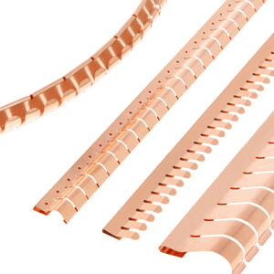
Our range of beryllium-copper fingerstrips and contact strips provides cost-effective long-term EMI/RFI shielding, without any risk of degradation as a result of repeated opening and closing of the enclosure, or of bending of the beryllium-copper fingers. The Be/Cu fingerstrip is also referred to as Be/Cu fingerstock.
How do Be/Cu fingerstrips work?
Modern electronic equipment often requires EMI/RFI shielding and an EMI/RFI-shielding gasket in order to avoid EMI/RFI radiation and to prevent interference from outside sources.
EMI/RFI gaskets that were designed and manufactured utilizing the strengths of beryllium and copper (Be/Cu) are the industry standard throughout the world. Starting with the emergence of RFI/EMI problems in the early days of military electronics, Be/Cu EMI/RFI shielding gaskets have been the solution of choice.
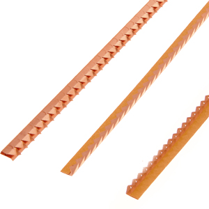
Be/Cu fingerstrips/fingerstock do two things very well
The mechanical spring characteristics of Be/Cu fingerstrips/fingerstock are far superior to all other EMI/RFI-shielding gaskets in the industry.
Be/Cu fingerstrips/fingerstock offer the highest EMI/RFI-shielding effectiveness.
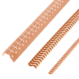
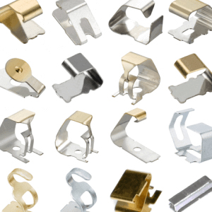
Custom-engineered stampings
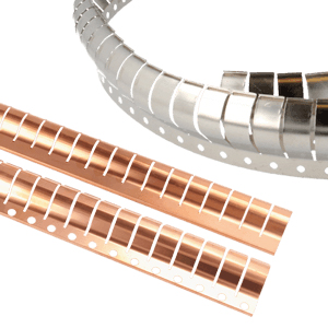
Apart from beryllium-copper, we also offer shielding and custom-engineered stamping in stainless steel, brass, phosphor bronze and other special alloys.
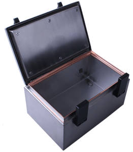
Example of a shielded box with a hatch and housing construction
Example of usage
Fingerstrips are often used in construction where a large spring range is required and the contact frequently is being pressed and released. Fingerstrips are in fact not very susceptible to wear.
Fingerstrips are widely used to make a good contact between hatch and housing or door and Faraday cage. An example of a shielded box with a hatch and housing construction is being displayed on the right.
Example of a shielded box with a hatch and housing construction
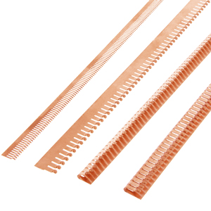
Large stock, quick delivery
The Be/Cu fingerstrips are available in a variety of surface finishes, with or without tape or conductive tape. These Be/Cu fingerstrips can be delivered within 5-10 working days.
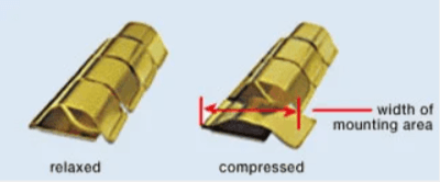
Determine the correct size of the mounting area (See Figure 1.)
2. Dynamic range of compression
Each shielding gasket is compressed to a certain distance, depending on the design. A positive contact force can usually be assured when the gaskets are compressed up to 25% of their relaxed height or more.
3. Attachment method
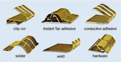
With the Holland Shielding Systems BV standard configuration there are the following mounting methods:
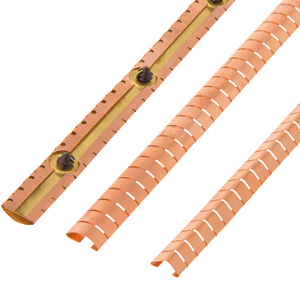
Clip-on mounting
Instant tac adhesive
Conductive adhesive
Solder
Weld
Hardware
For more information see Figure 2.
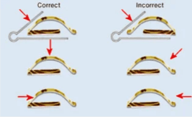
4. Correct orientation
Many of our gasket designs depend on the active contact surface (top) being engaged at, or behind, the cross-sectional centre line. To assure the proper angle of engagement, the guidelines below should be followed for best results.
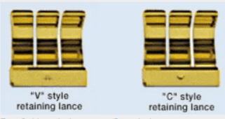
Retaining lances for clip-ons
Most clip-on styles are available with retaining lances which enhance the spring grip onto the mounting surface.
Adhesive tape specifications
Our shielding designs incorporate two types of adhesive tape on many of the gaskets.
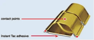
Instant tac adhesive
Application: for areas where the two opposing surfaces can be connected by contacting at least one point of the shielding gasket’s profile on each surface.
Temperature range: -50 °F (-46 °C ) to +300 °F (+149 °C)
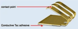
Conductive tac adhesive
Application: for areas where the two opposing surfaces can be connected by contacting one point of the shielding gasket’s profile on one side and Conductive tac on the other. Temperature range: -50°F (-46 °C ) to +300 °F (+149 °C)
Fig. 1. Determine the correct width of the mounting area
Fig. 2. Attachment methods
Fig. 3. V-style lance vs. C-style lance
Fig. 4.
Fig. 5.
Fig. 6. The correct way to exert force on the fingerstrip